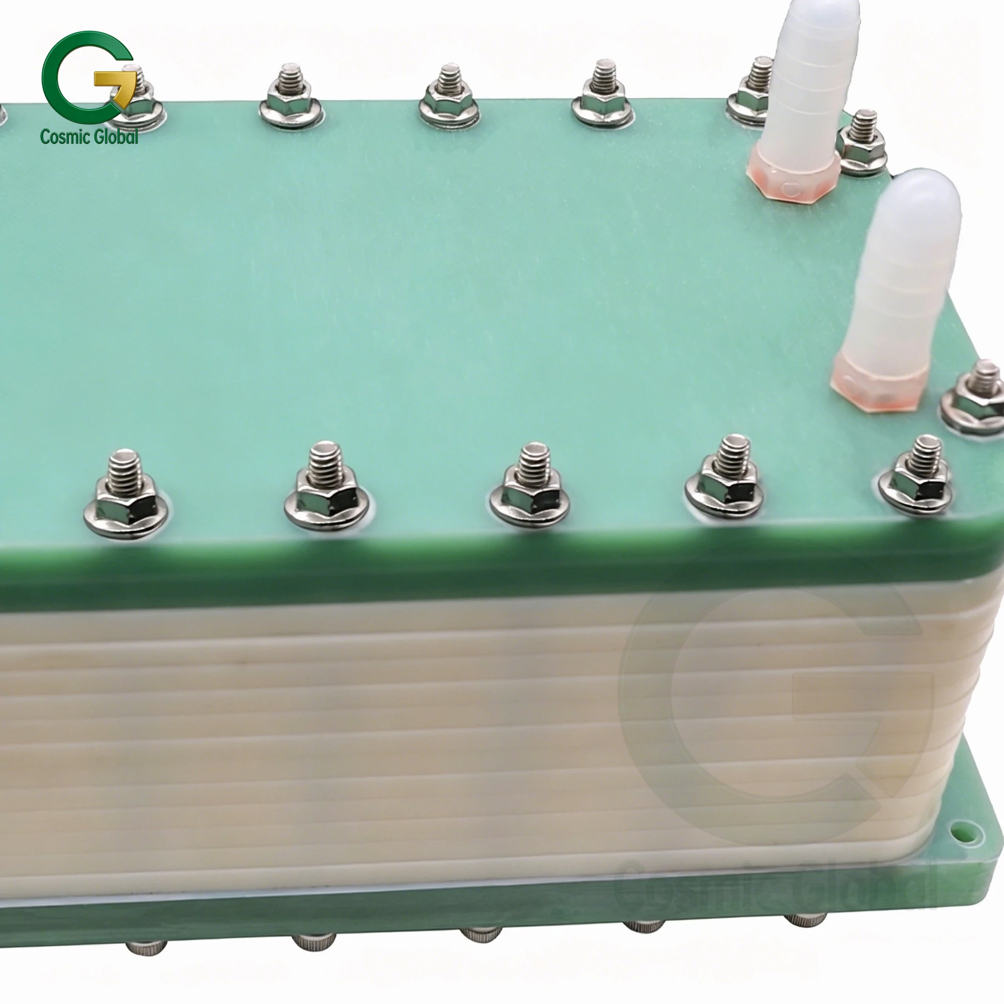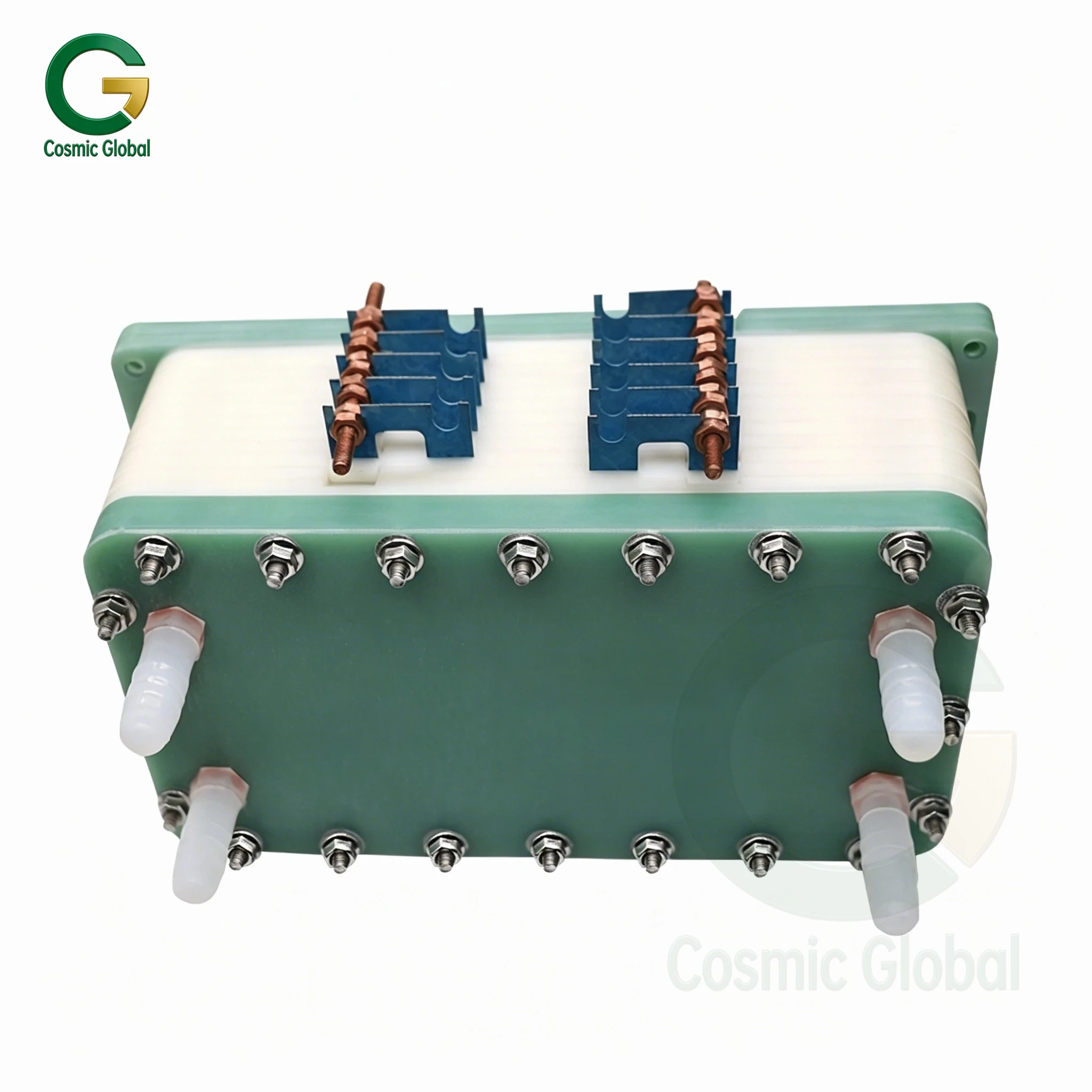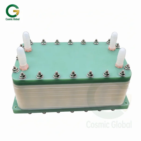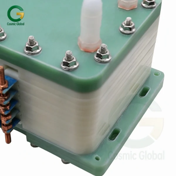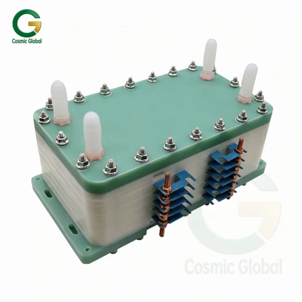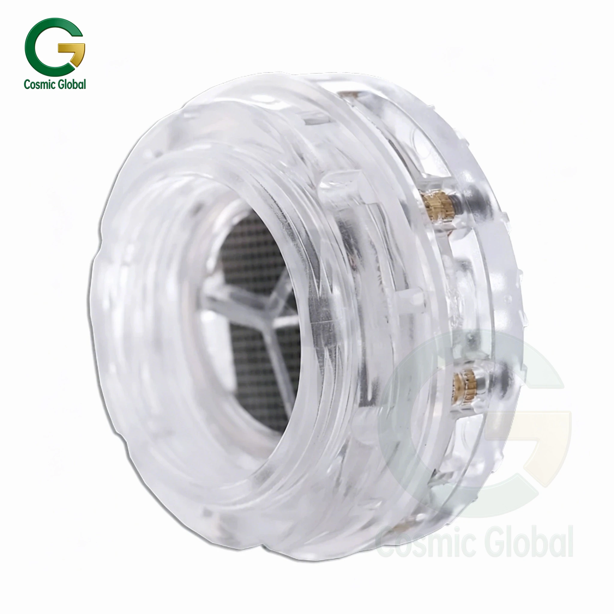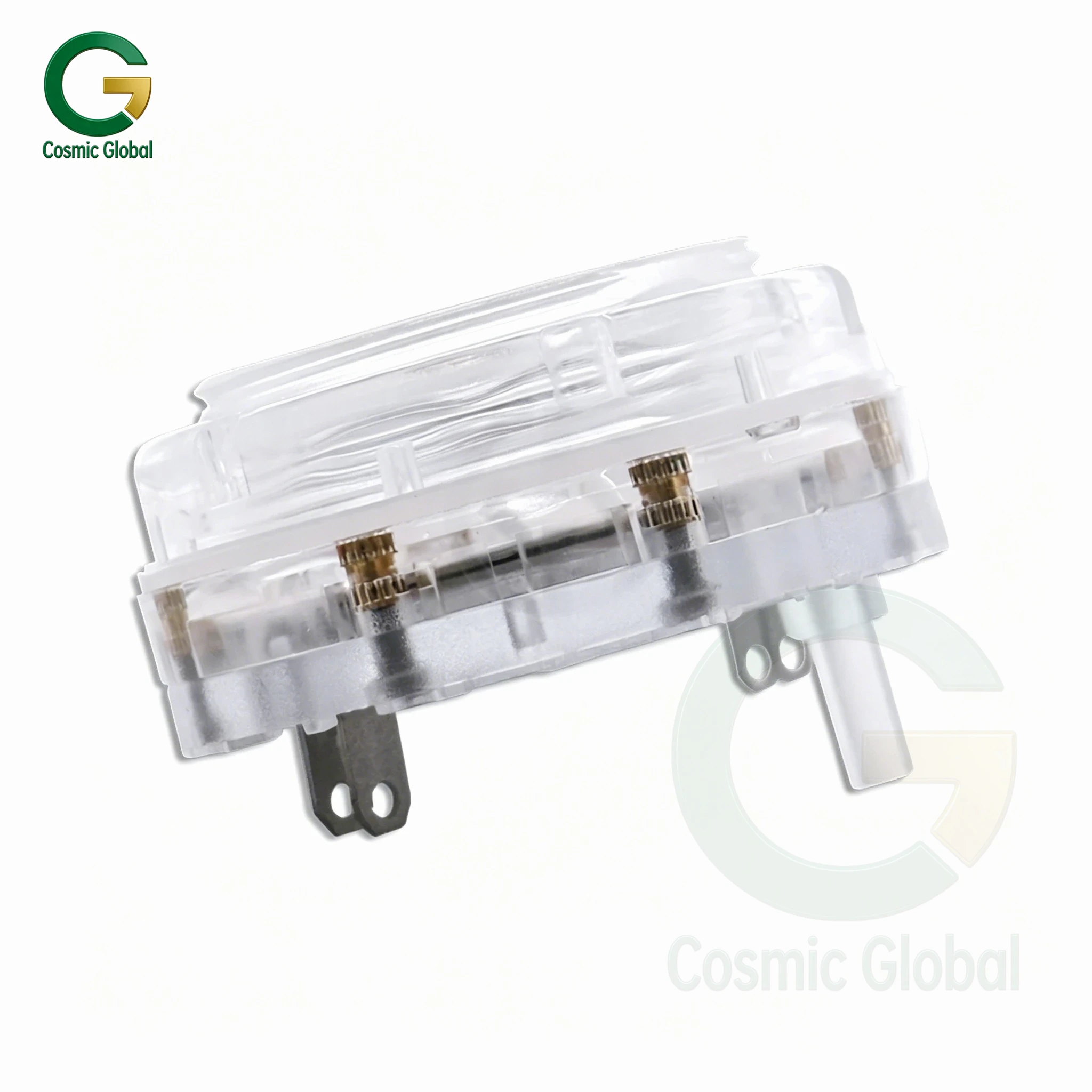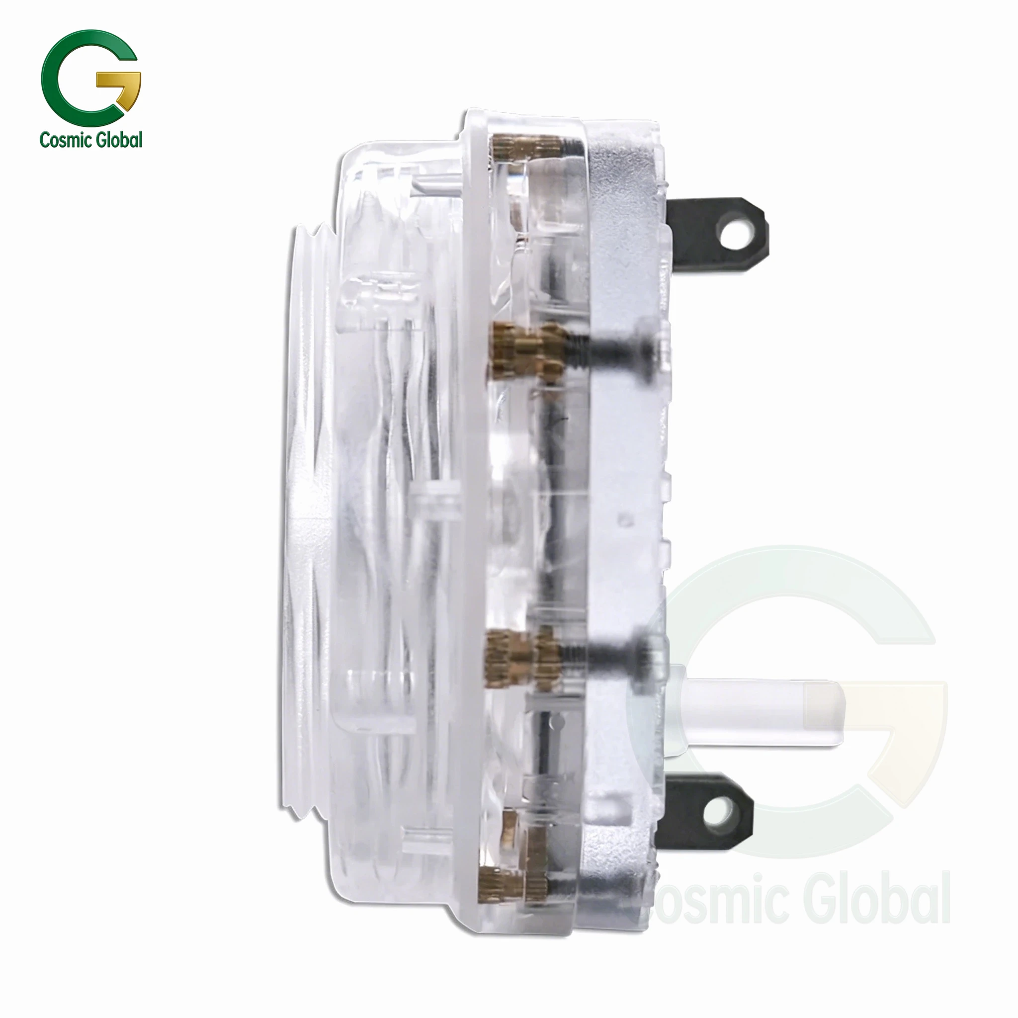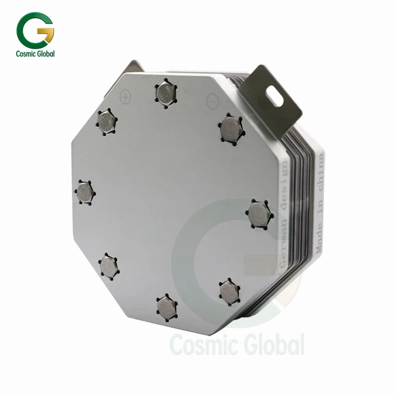
character ist ics :
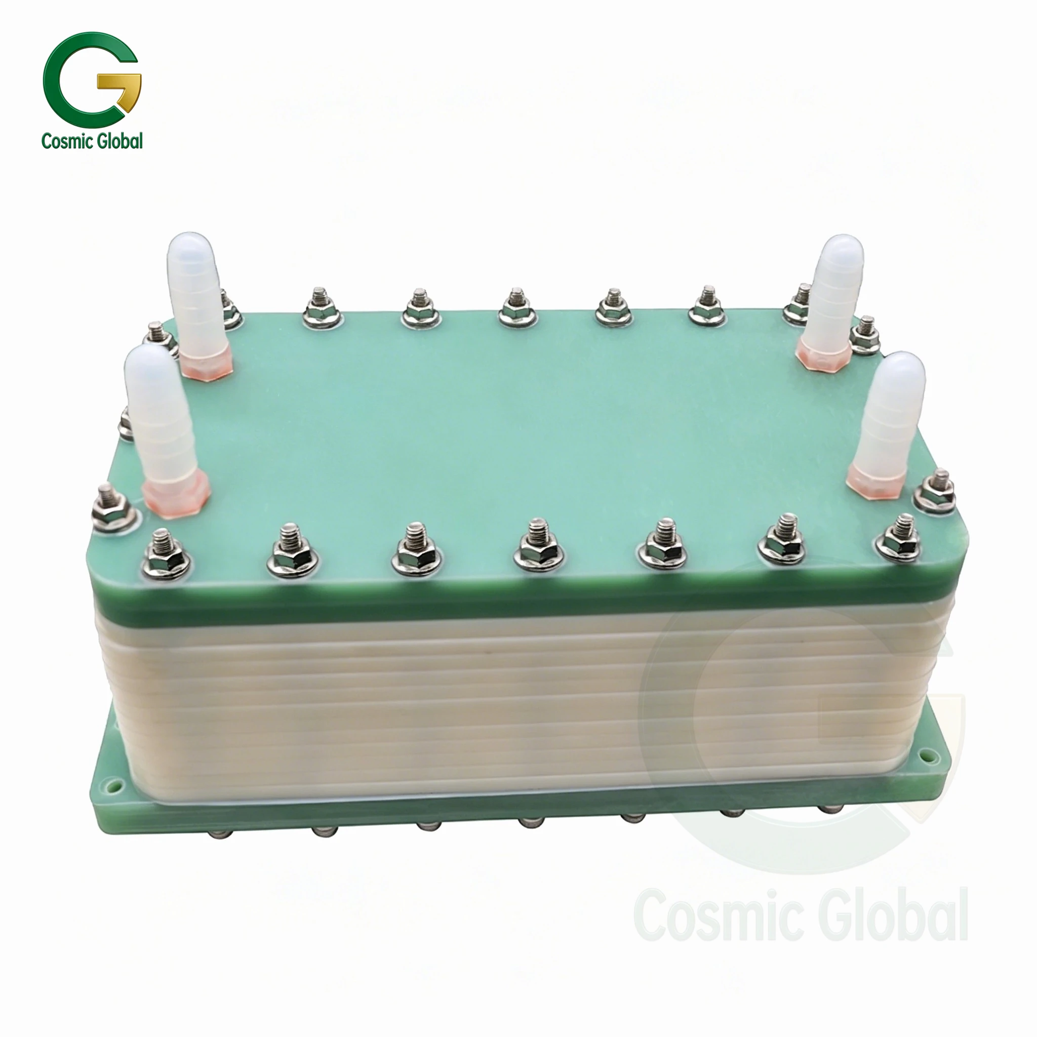
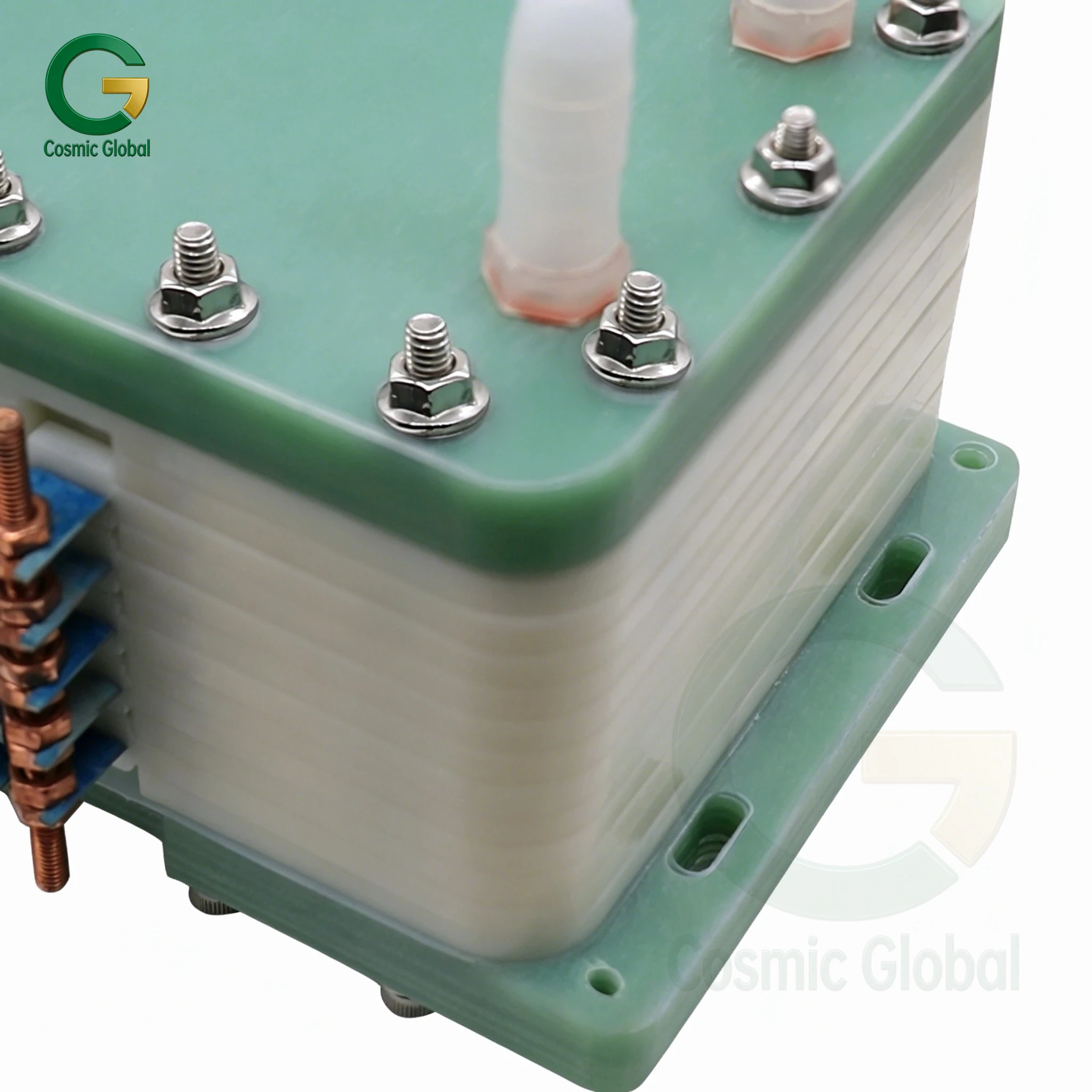
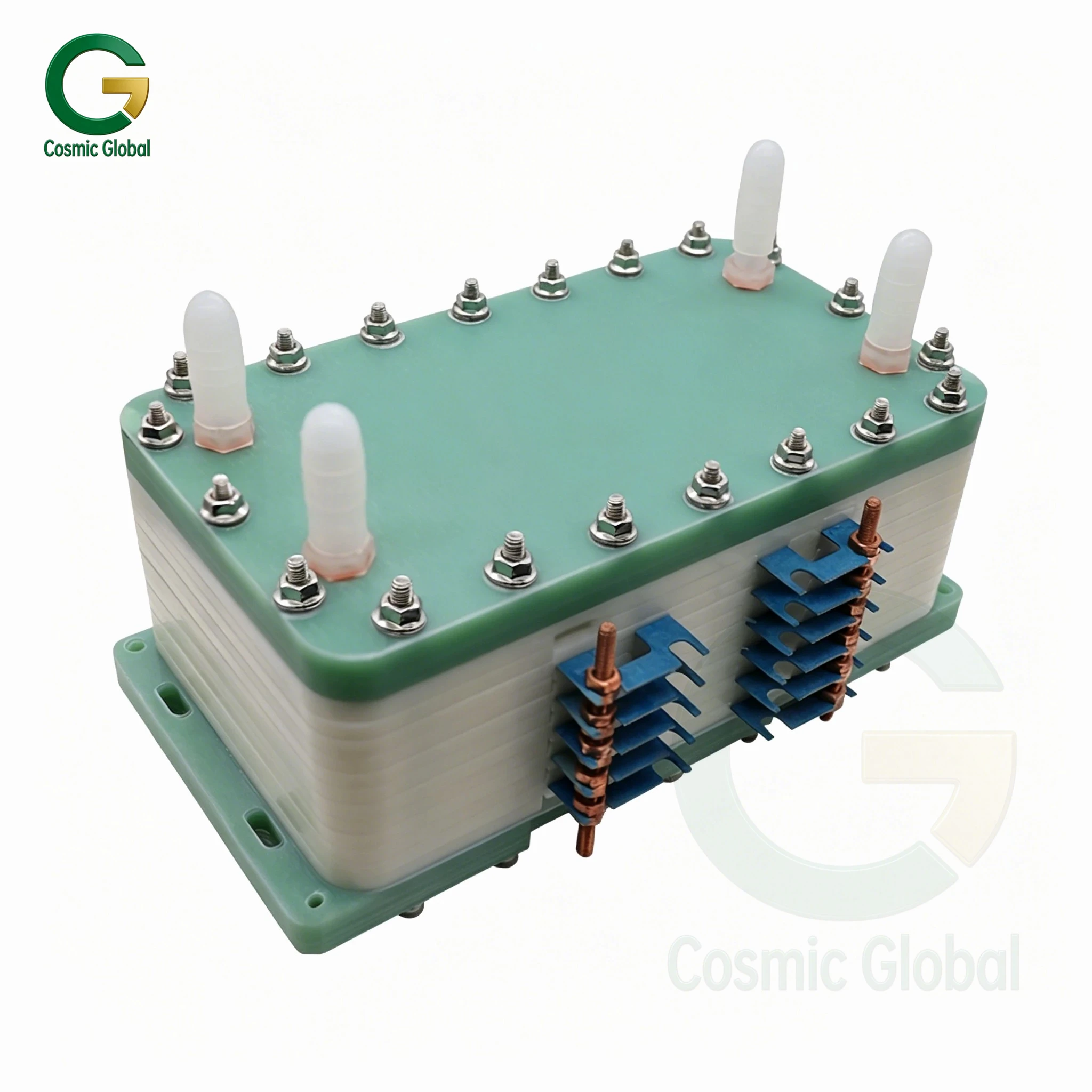
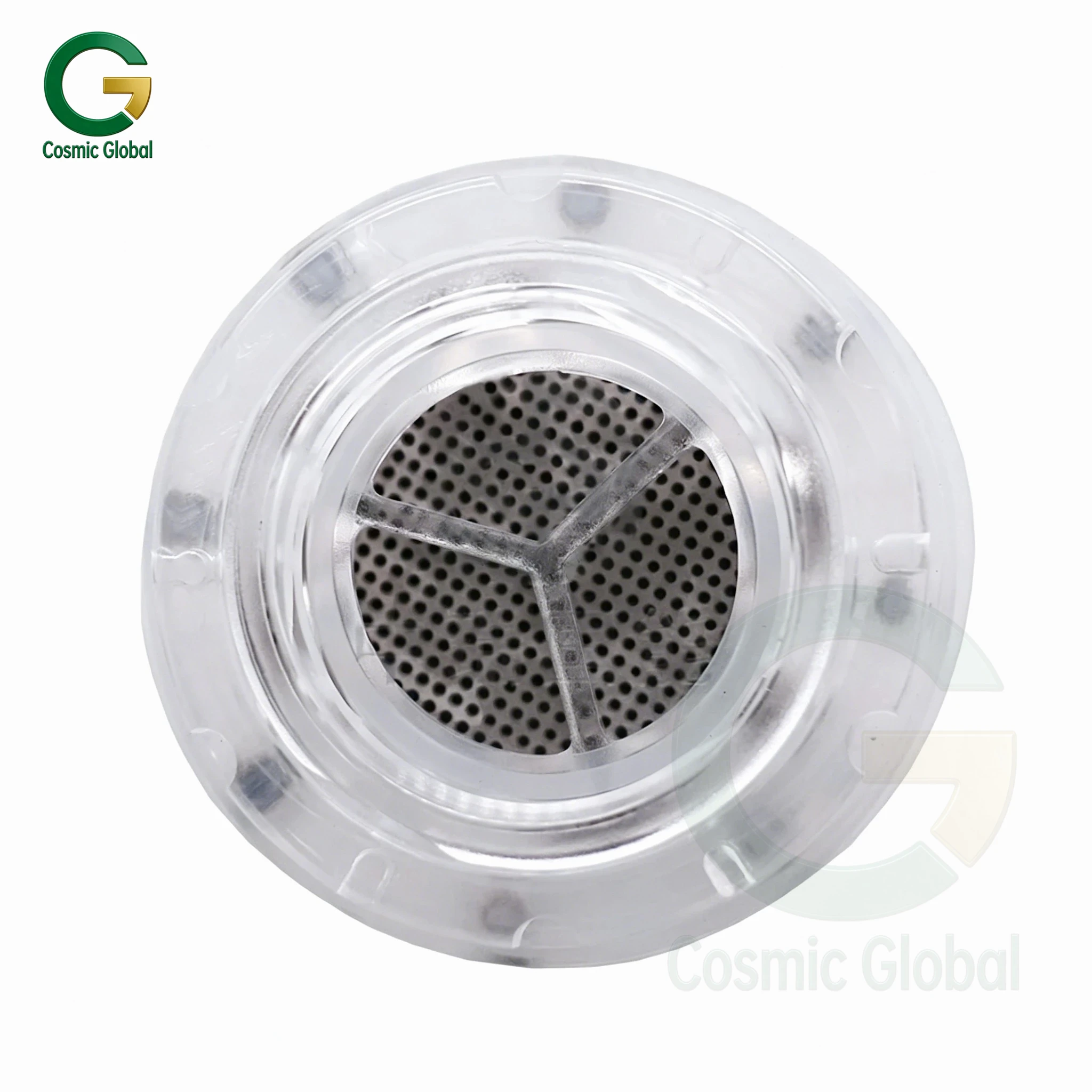
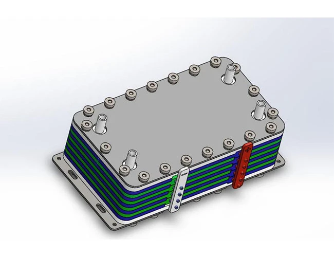
● Pure water inputs —— acid + alkaline water outputs Multistage diaphragm electrolysis, integrated design
● Titanium noble metal electrodes, environmentally friendly andpollution-free
● Superposition design, flexible
● Acid potent ial water app l icat ions :
● Medical disinfection
Washing, soaking and disinfecting of utensils, utensils and utensils
● Wash and disinfect fruits, vegetables and raw food
● Environmental disinfection
● alkal ine potent ial water
app l icat ions :
Drinking weak alkaline water PH 7-8 Cleaning and deoiling
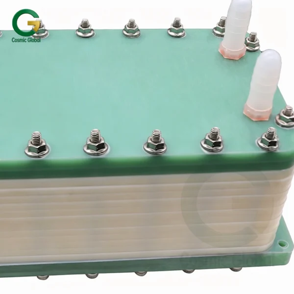
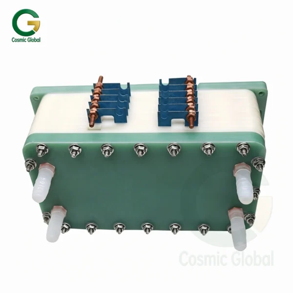
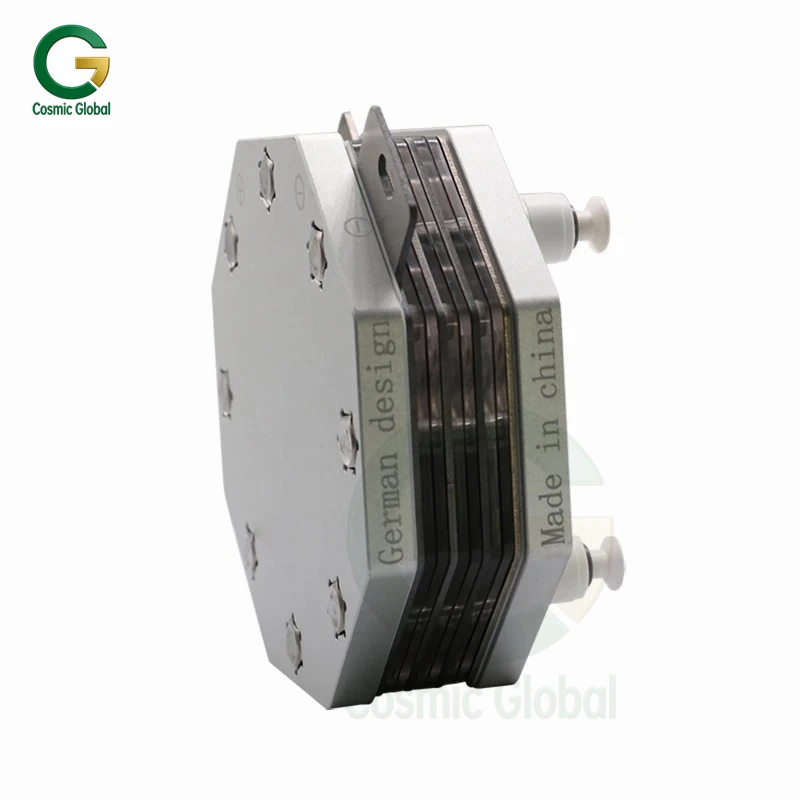
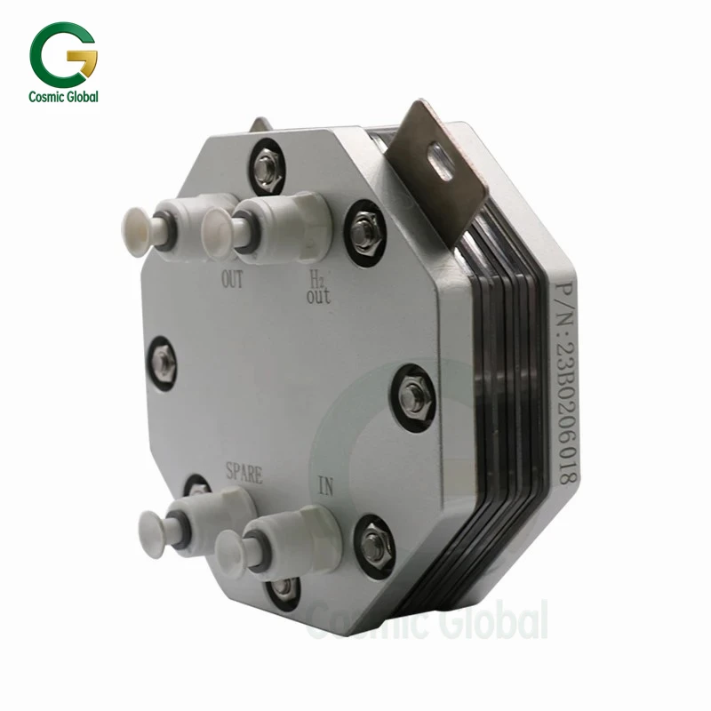
Description of ZR20-20-001 acid/alkali electrolyzer specifications:
● Electrolyticcellscan simultaneously produce acid and alkaline potential water.
● Theoutputacid/alkali water ratio can be adjusted flexibly, and by default the acid/alkaline water ratio is 1 :1.
● Ifit is necessary to adjust the proportion of the effluent, the appropriate throttling device should be matched to adjust the range :
The ratio of acid water to alkaline water is 5 :1.
The ratio of alkaline water to acid water is 5 :1.
● Electrolyticcellscan be stacked PH layers according to the range of values required by the customer, with an optional range of 3,5,7,9,11.
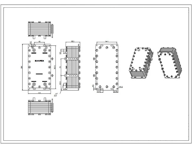
Dimensions:
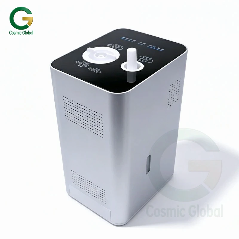
System support
requirements:
Installation instructions:
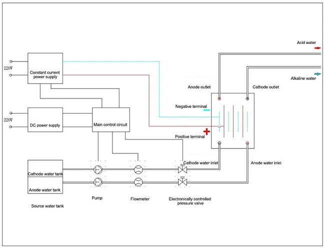
1.electrolytic cell issuppliedby constant current power supply.
Electrolytic cells need to be equipped with electrolytic power supply control system and electrolyte water supply control system.
Requirements for supporting equipment are shown in the table of basic parameters.
The power supply system and the liquid supply system cooperate with each other. When the water is supplied, the electrolytic power supply begins to supply the power to the electrolytic cell.
● Equipmentrequiresthree protections :
1.Constant current power supply itself overcurrent, overvoltage protection.
2.Pressure monitoring of the pipeline requires a pressure release device.
The system needs to monitor the influent flow of anode chamber and cathode chamber. Once the liquid supply is cut off, the electrolytic power supply is cut off in time to avoid equipment damage.
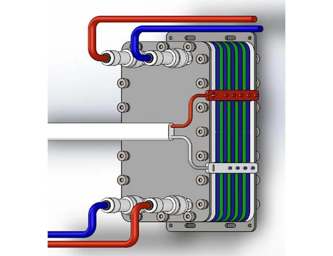
Acid effluent Alkaline water
Cathode chamber inlet Anode chamber inlet
Electrolytic Power Supply
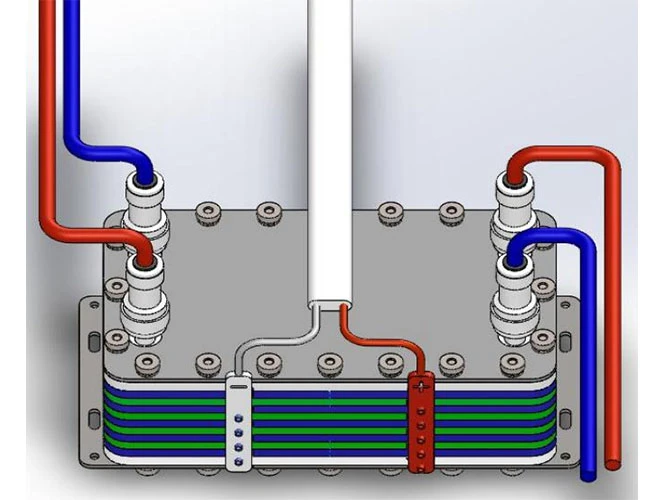
● electrolytic cellinlet andoutlet using 3 ´ fast joint.
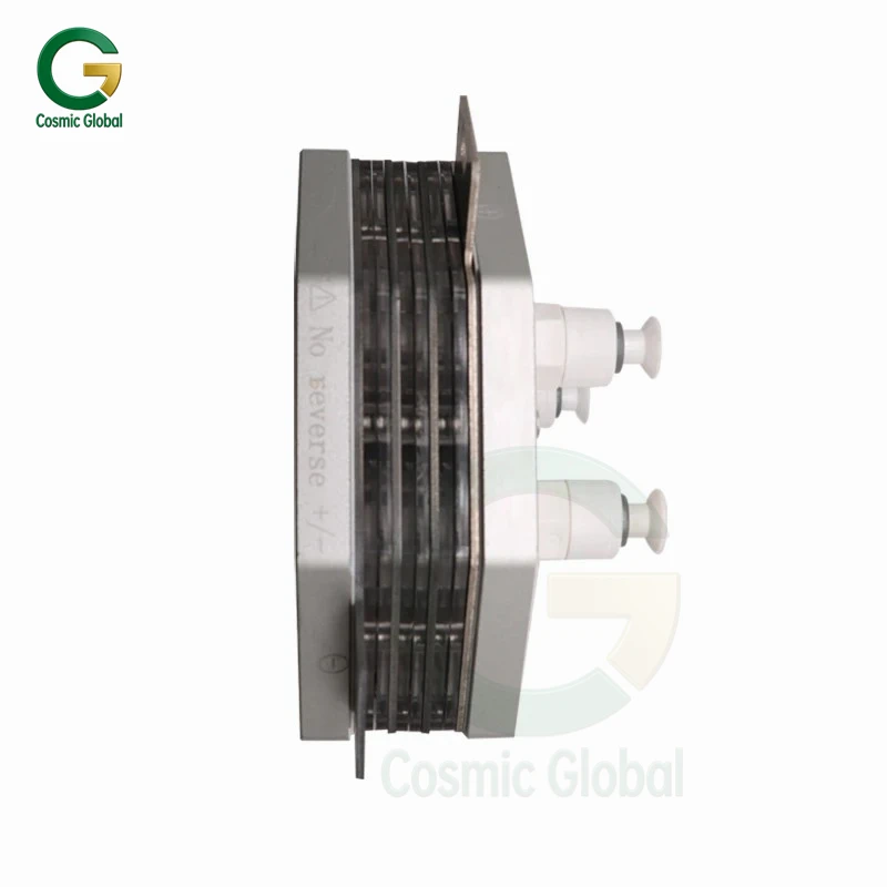
● positive and negative electrode ofelectrolyticcell can beconnected by 6.3 spring end, and the matching copper core soft wire connection can be selected according to the corresponding number of layers.
equipmentsupporting powersupply according to the number of different layers are:
|
3 layers |
5 layers |
7 layers |
9 layers |
11 layers |
| Power supply current |
A 0-5 |
A 0-10 |
A 0-15 |
0-18 A |
A 0-22 |
| Power supply voltage |
V 0-36 |
V 0-36 |
V 0-36 |
V 0-36 |
V 0-36 |
● electrolyticcell installation needs to be erected, water inlet and outlet convenient exhaust.
Note: the inlet and outlet water interface of electrolytic cell is fragile.
Basic parameters:
| Project |
3PCS |
5PCS |
7PCS |
9PCS |
11PCS |
| Dimensions |
206 mm×105 mm |
206 mm×105 mm |
206 mm×105 mm |
206 mm×105 mm |
206 mm×105 mm |
| 66.5 mm thickness |
76.5 mmthickness |
| 35 mm thickness |
45 mm thickness |
55 mm thickness |
| Use of water pressure |
≤0.2 MPa |
≤0.2 MPa |
≤0.2 MPa |
≤0.2 MPa |
≤0.2 MPa |
| Working temperature |
0-40℃ |
0-40℃ |
0-40℃ |
0-40℃ |
0-40℃ |
| Water intake Water Electrolysis |
1-2 L/min |
1-2 L/min |
L/min 2-3 |
L/min 2-3 |
2-3/ min / |
| Water output from alkaline water |
1-2 L/min |
1-2 L/min |
L/min 2-3 |
L/min 2-3 |
L/min 2-3 |
| Water electrolysis Water output from acid water |
1-2 L/min |
1-2 L/min |
L/min 2-3 |
L/min 2-3 |
2-3/ min / |
| PH value of alkaline potential water |
7-9 |
7-10 |
7-10.5 |
7-11.5 |
7-11.5 |
| Acid potential water PH value |
4-7 |
3-7 |
2.5-7 |
2-7 |
1.5-7 |
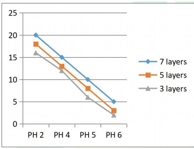
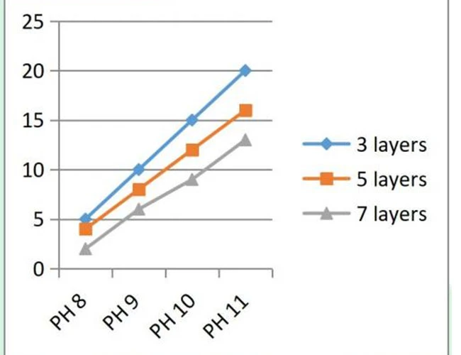
Layer number, current, PH value curve
Current — a lkal ine water
current — acid water
Environmental adaptability
refer to CAS 124-007、GB12176-1990、GB/T 19774-2005 standard for sealing performance, water pressure resistance, electrolysis
performance, durability requirements and test methods.
Associated test items : (below are 5 samples pcs noble metal coated electroly zer)
| No. |
Test Item |
Test Conditions |
Remarks/Required Equipment |
| 1 |
Sealing Performance |
Seal the inlet and outlet of the electrolytic cell, apply a water pressure of 0–0.2 MPa to the inlet, and ensure there are no leaks for 1 minute. |
Pressure Pump |
| 2 |
Hydrostatic Pressure Resistance |
Seal the outlet of the electrolytic cell, apply a water pressure of 0.2 MPa to the inlet for 5 minutes, and ensure the equipment remains undamaged and leak-free. |
Pressure Pump |
| 3 |
Electrolytic Performance |
With water flowing through the electrolytic cell and a dynamic pressure of the water source ≤ 0.2 MPa:
1. Inlet flow rate: 2 L/min; source water conductivity: >60 µs/cm; electrolytic current: 5 A;
2. Inlet flow rate: 2 L/min; source water conductivity: <30 µs/cm; electrolytic current: 3 A;
After the above conditions have stabilized for 10 seconds, collect at least 150 mL of electrolyzed water. Measure the pH using a glass-electrode pH meter and the hydrogen concentration using a hydrogen meter; both must meet specification requirements. |
DC Power Supply, Water Pump, pH Meter, Hydrogen Concentration Meter |
| 4 |
Durability |
Feed water flow rate: 2 L/min; source water dynamic pressure ≤ 0.2 MPa; electrolytic current: rated current of 3 A; one cycle consists of 15 minutes of forward and 15 minutes of reverse electrolysis; 1,500 consecutive cycles; total operating time: 750 hours; after testing, performance items 1–3 meet the requirements |
DC Power Supply, Water Pump |
| 5 |
Low-Temperature Storage Test |
After being placed in a sub-zero temperature environment for 4 hours, the sample’s appearance, structure, and primary performance meet the requirements |
Low-Temperature Test Chamber |
| 6 |
Packaging Vibration Test |
10–30–55 Hz sine wave sweep, amplitude 0.75 mm, 1 octave per minute, 15 minutes each in the X, Y, and Z directions (45 minutes total) |
Variable-Frequency Vibration Test Stand (in standard product packaging) |
Service life:
Operating time ≥5000 h. at room temperature, normal atmospheric pressure, external standard power supply and water source
Reliability requirements
The reliability of the electroly zer is represented by an average failure-free time MBTF: MTBF ≥5000 h.
Safety performance
1.a) the electroly zer is a low voltage and weak current input, there should be no danger of ignition caused by electric shock or temperature rise;
2.b) the electrolytic cell in the correct use, there should be no damage or leakage phenomenon;
3.c) the electrolytic cell in correct use, the touchable element should not be charged.
Product label: model, format, serial number (not repeated)
Packaging, Transport and Storage
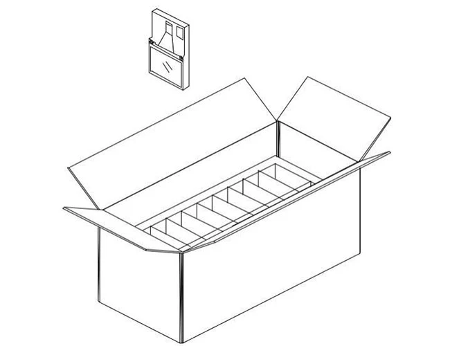
1) Supply Packing
Packaging specifications :570 (L)×270 (W ) ×280 (H) mm
Packing Weight :5 Kg
Number of packages :5 (each packed in bubble bags)
2) sample packaging
Packaging specifications :230 (L) ×120 (W) ×55-115 (H) mm
Packing list :1 (packed in self-sealing bags)
3) Transport and Storage
Avoid collision and rain and snow during transportation; store with chemicals and damp items.
Schematic illustration of outer box specifications: