
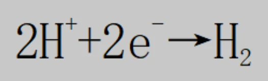
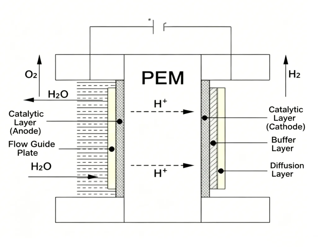
Proton Exchange Membrane (PEM) water electrolysis technology for hydrogen production utilizes a polymer membrane with proton-conducting properties as the electrolyte; the separator within the electrolyzer cell consists primarily of this proton exchange membrane. In a PEM water electrolyzer, water is decomposed at the anode into oxygen (O2), electrons (e-), and protons (H+), with the oxygen being discharged from the anode. The electrons flow through an external circuit toward the cathode, while the protons migrate through the proton exchange membrane to the cathode. On the cathode side, two protons and two electrons recombine to produce hydrogen gas (H2).
Compared to alkaline (ALK) electrolyzers, PEM electrolyzers offer distinct advantages
—such as high current density, high hydrogen purity, and rapid response speed
—making them particularly well-suited for integration with wind, solar, and energy storage technologies.
Operating Principle of Hydrogen Electrolyzers
Our hydrogen generators utilize the company’s proprietary PEM technology. Purified water meeting the requirement of a TDS level of zero is fed into the electrolytic cell. Through the electrolytic splitting of water powered by electrical energy, oxygen, hydrogen ions, and electrons are generated within the anode chamber. The hydrogen ions (H+) then migrate through a proton exchange membrane to the cathode chamber, where they absorb electrons to form hydrogen gas; this gas is subsequently discharged from the cathode chamber into a gas-water separator, yielding a high-purity output.
Anode reaction:

Cathode reaction:
Scope of Application
As a core component of pure water electrolysis hydrogen production equipment utilizing the PEM process, this unit can generate 0 –100 Nm³/h of hydrogen, tailored to specific user requirements.
Structural Information
A PEM hydrogen electrolyzer typically consists of a stack of multiple individual cells.
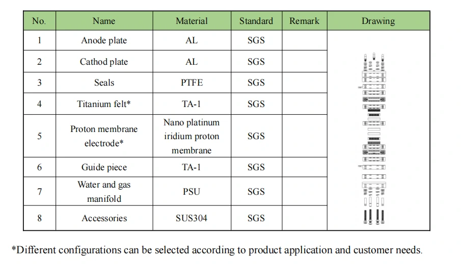
Moving outward from the center, each cell is sequentially composed of a membrane electrode assembly (MEA), titanium felt, a multi-layer titanium mesh, a water-vapor separator, titanium anode and cathode plates, and anode and cathode faceplates.
The MEA serves as the core of the PEM electrolyzer; it consists of a proton exchange membrane, a catalytic layer, and a gas diffusion layer. The proton exchange membrane functions simultaneously as both a separator and an electrolyte; the material currently most widely used for this purpose is perfluorosulfonic acid. Zhongrui Guoneng’s MEAs utilize an aqueous slurry formulation and employ a platinum-iridium alloy for the catalytic layer; by leveraging advanced international nanotechnology, these MEAs exhibit exceptionally high electrochemical activity and superior stability.
In the PEM electrolyzer, the titanium felt functions as the gas diffusion layer; coated with platinum, it offers high electrical conductivity and a long operational lifespan.
The multi-layer titanium mesh is fabricated from pure titanium mesh sheets that undergo a multi-layer vacuum sintering process; it serves the dual functions of gas diffusion and liquid flow guidance.
The water-vapor separator is constructed from food-grade polycarbonate (PC) material, capable of withstanding temperatures up to 300°C while ensuring high pressure resistance and exceptional sealing integrity.
Both the anode and cathode are platinum-coated titanium electrodes. Their fabrication incorporates a proprietary coating technology—exclusive to Zhongrui Guoneng and protected by an invention patent—which ensures high energy conversion efficiency.
The faceplates are constructed from metal materials, providing robust structural support and protection for the assembly.
Storage Requirements
The electrolytic cell must be stored at ambient temperature (25±5°C). Exposure to direct sunlight or freezing environments is strictly prohibited.
The electrolytic cell must be kept filled with water; the water level should be checked periodically. It is strictly forbidden to remove the sealing plugs, as doing so would lead to water loss and drying out, which will negatively impact the cell’s performance.
If the electrolytic cell is to remain unused for an extended period, it is recommended that the pure water inside be replaced every 30 days, after which the cell should be refilled (with pure water) for continued storage. If conditions permit, the cell should also undergo an activation cycle every 30 days. (Refer to the “Activation Procedure” section for the specific method.)
Activation Procedure: Connect the electrolytic cell to a pure water supply and an adjustable DC power source, ensuring that all connections—particularly the water pump inlet—are correctly aligned with the designated ports. Ensure that water flow is established *before* applying power to the cell (Note: A water pump *must* be used to supply water, with an inlet flow rate exceeding 500 ml/min). Gradually increase the current at a rate of 1 Ampere every 3 minutes (e.g., maintain a current of 1A for 3 minutes, then 2A for 3 minutes, and so on, until the nominal operating current is reached). Subsequently, decrease the current at a rate of 1 Ampere every 3 minutes, reversing the process from the nominal current back down to 1A. Repeat this entire cycle 1–2 times to complete the activation process.