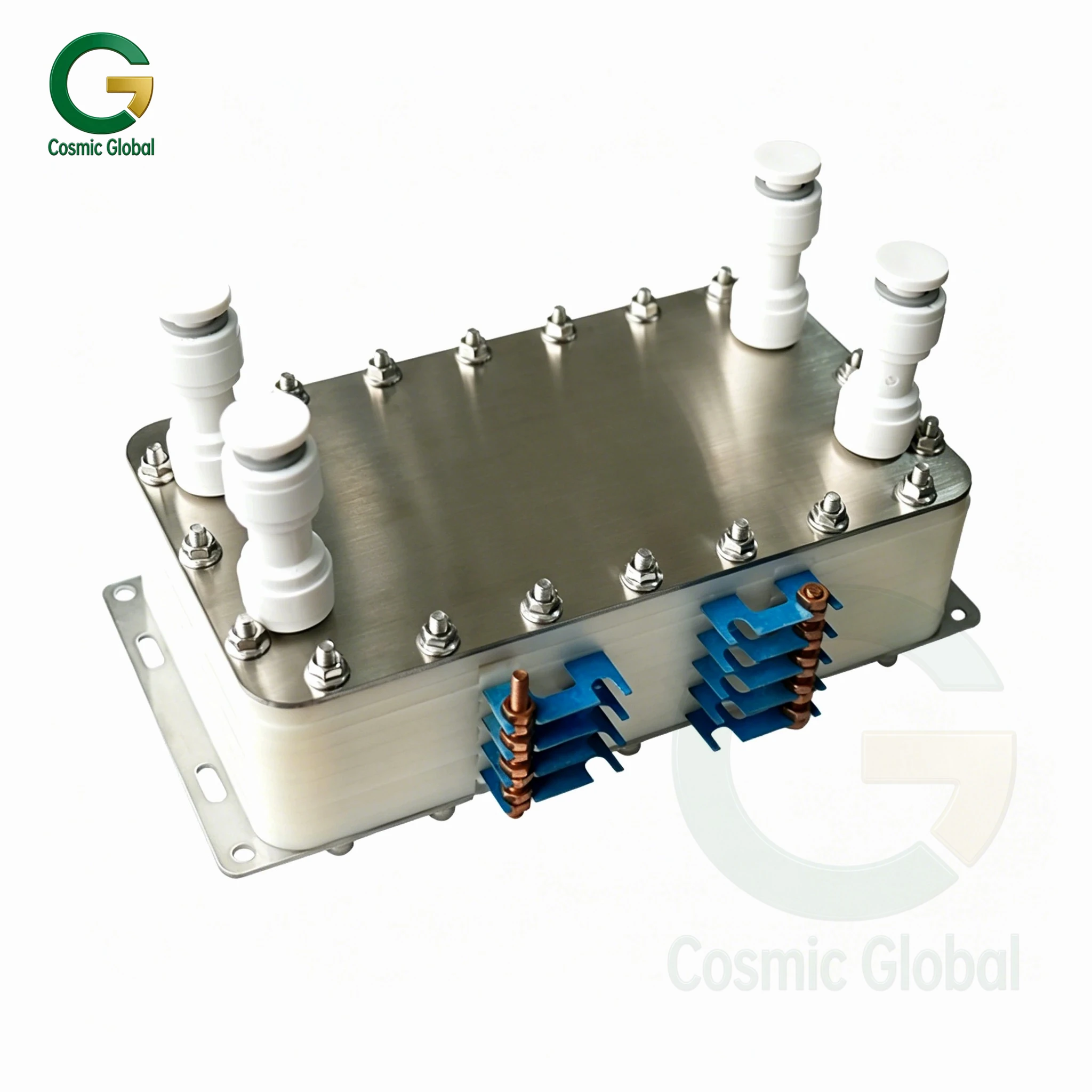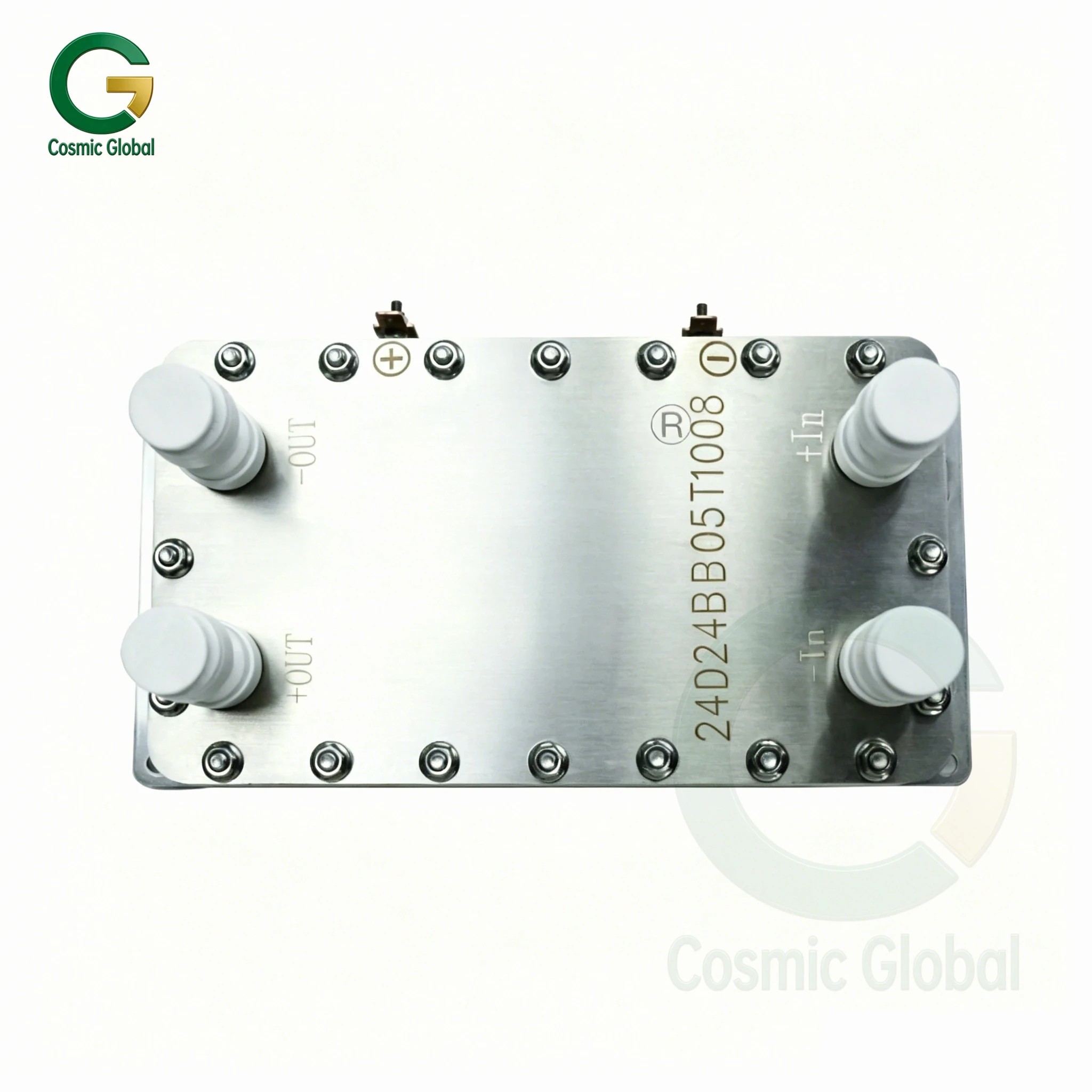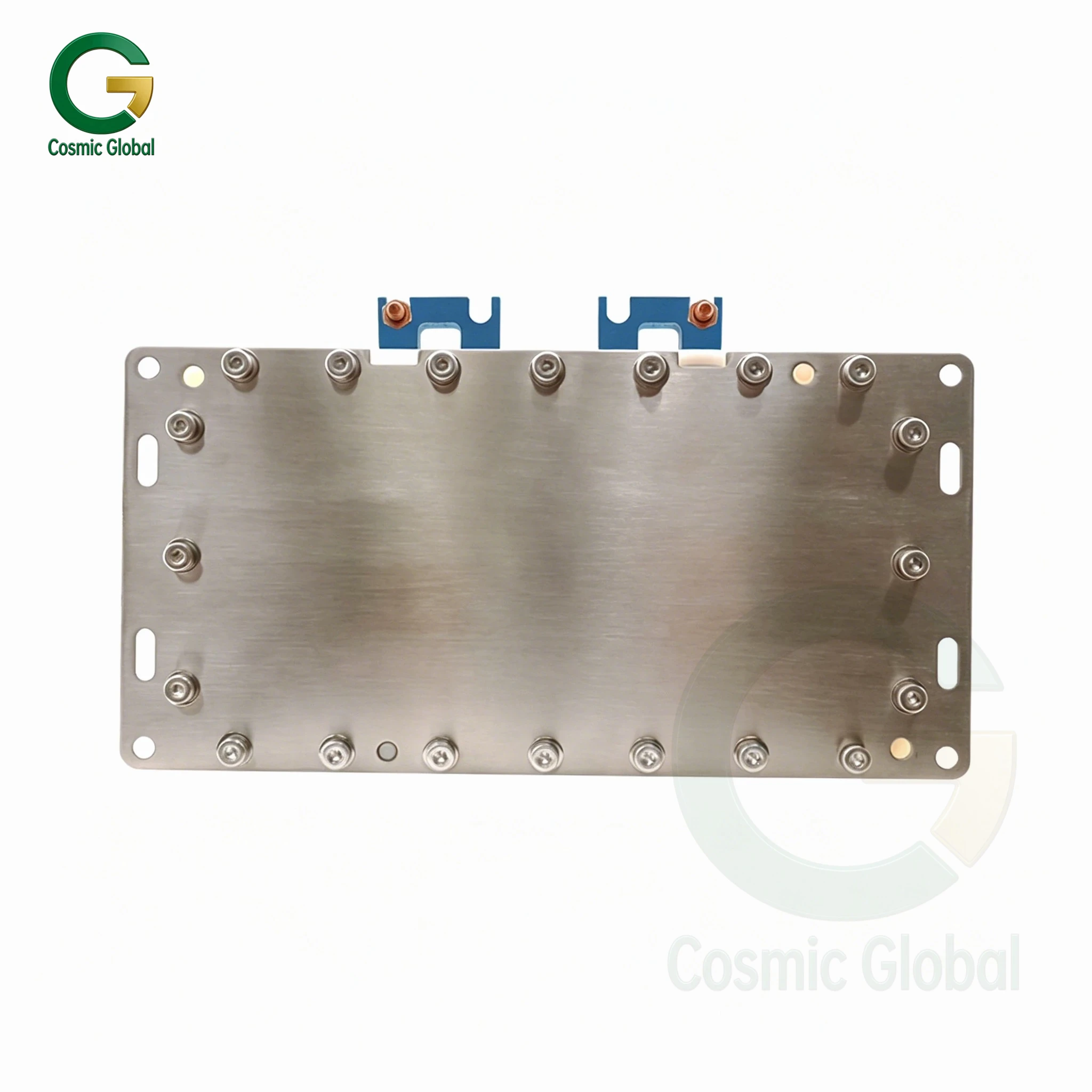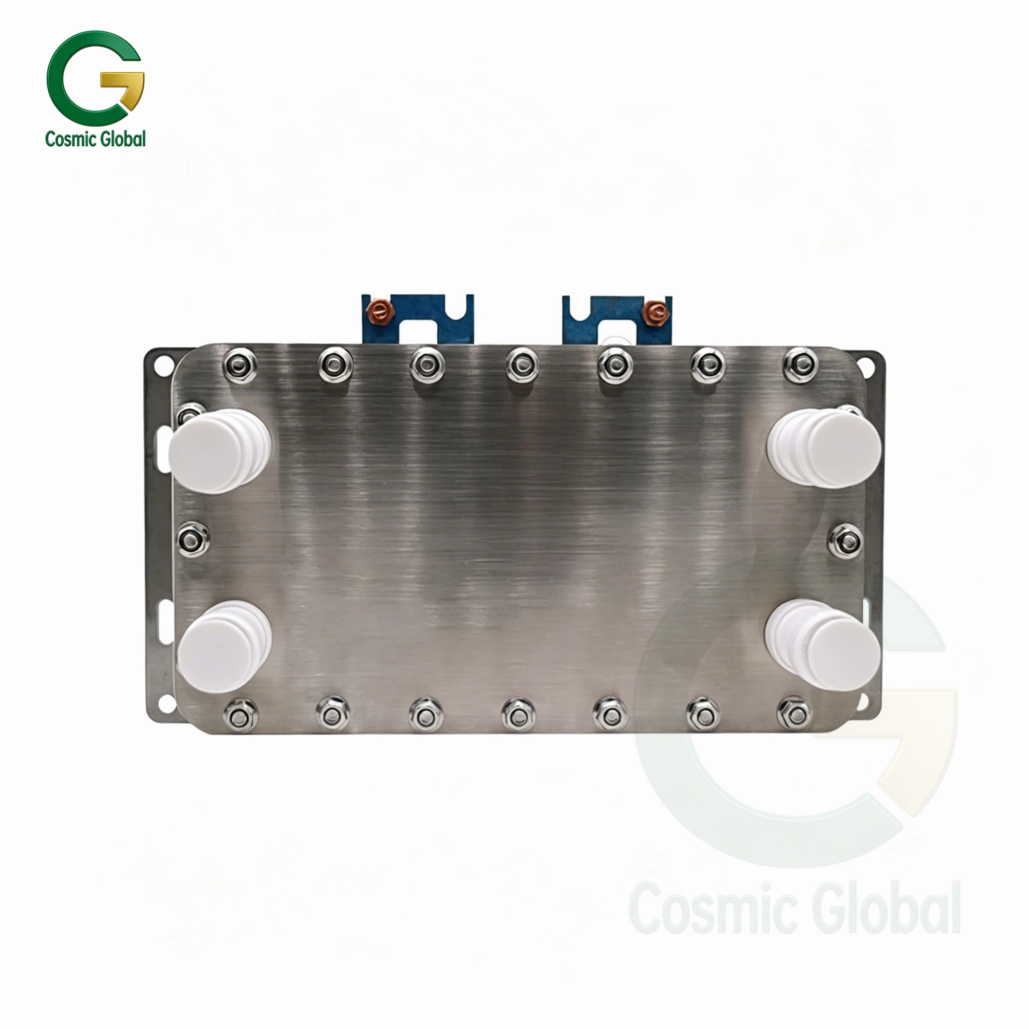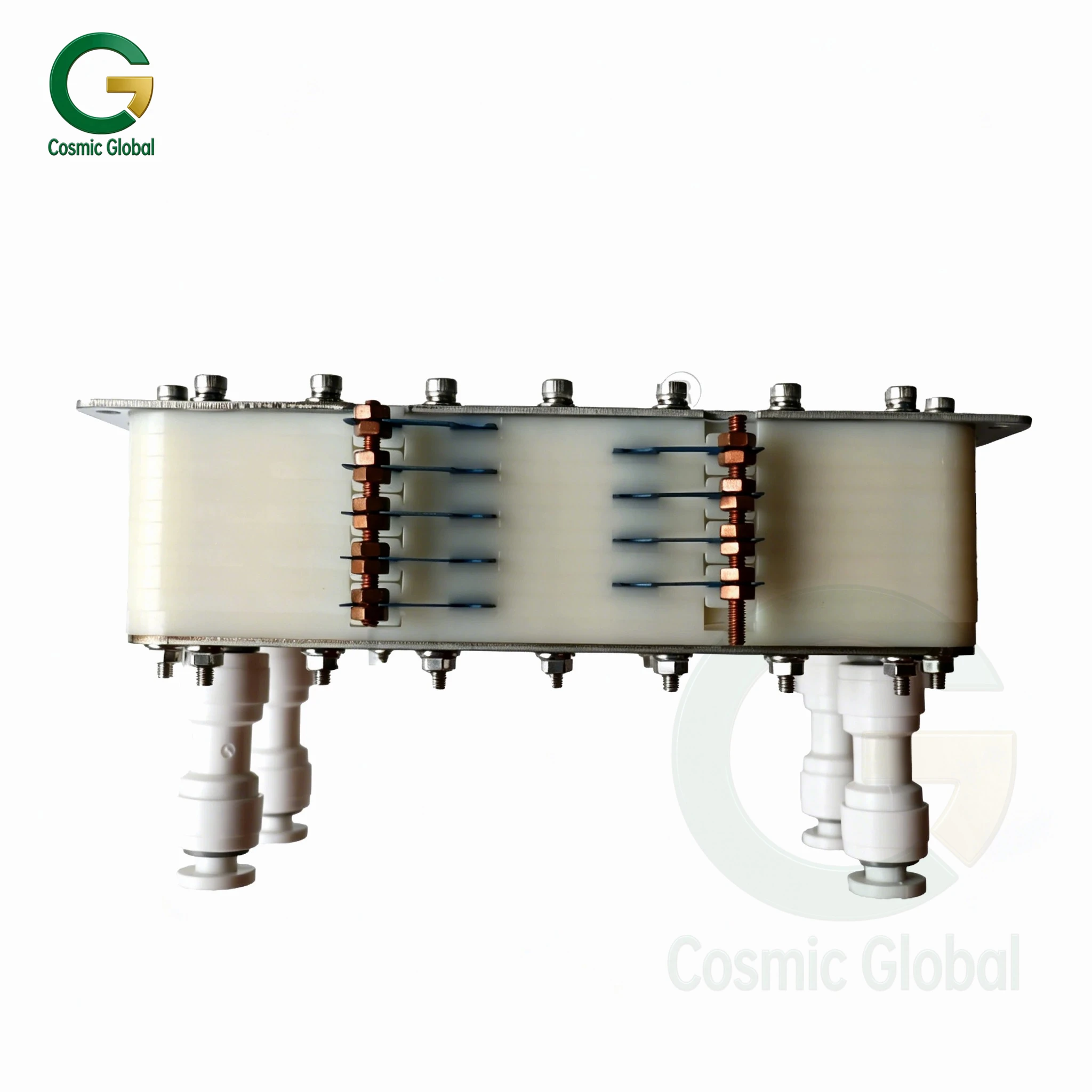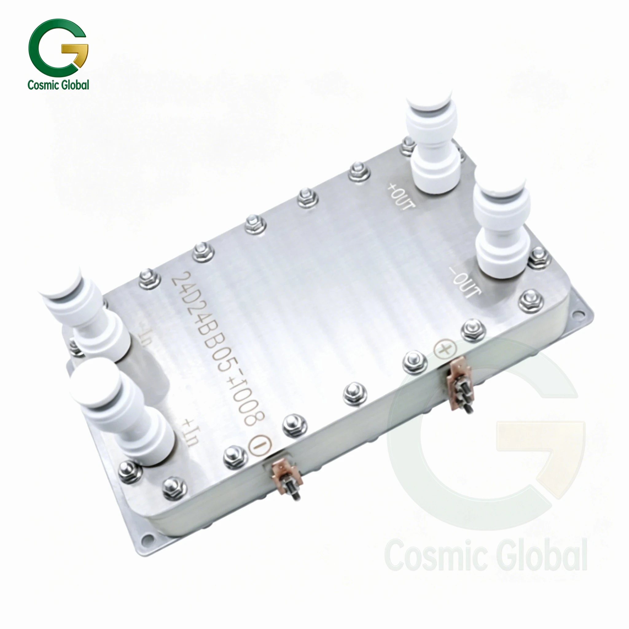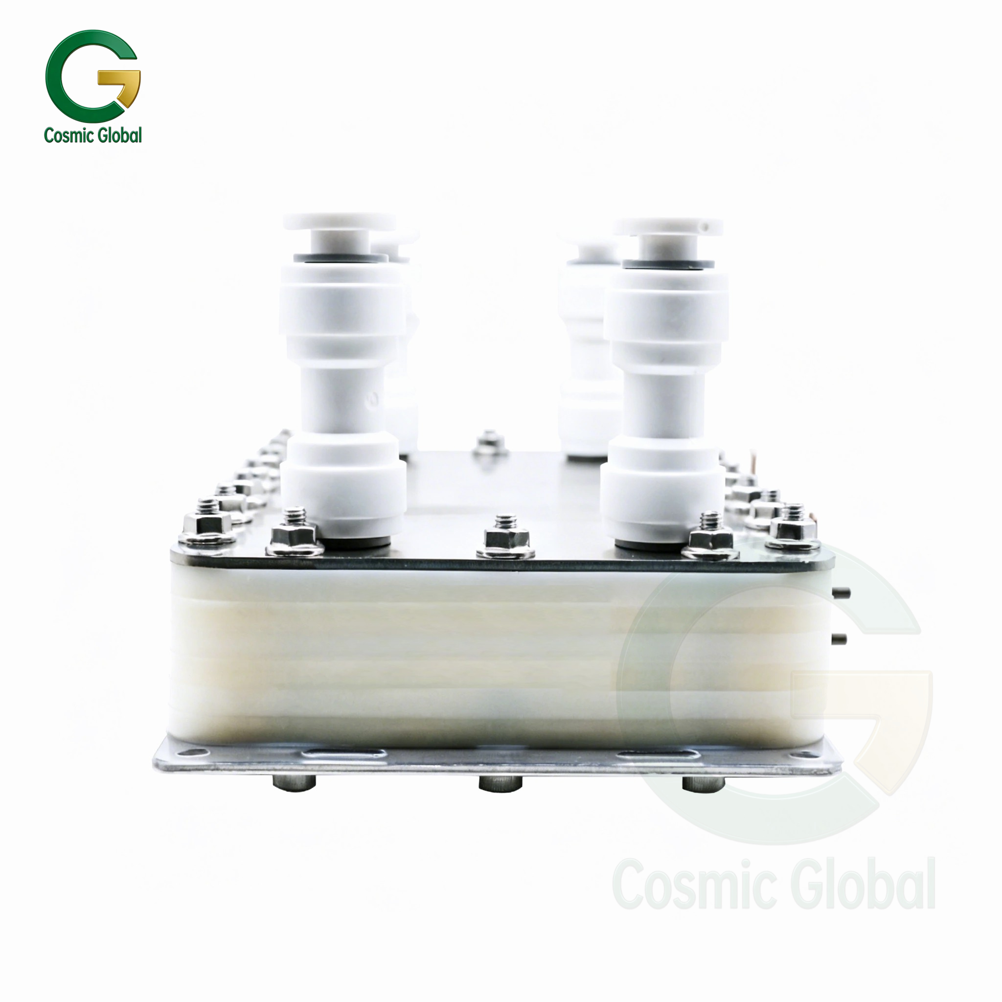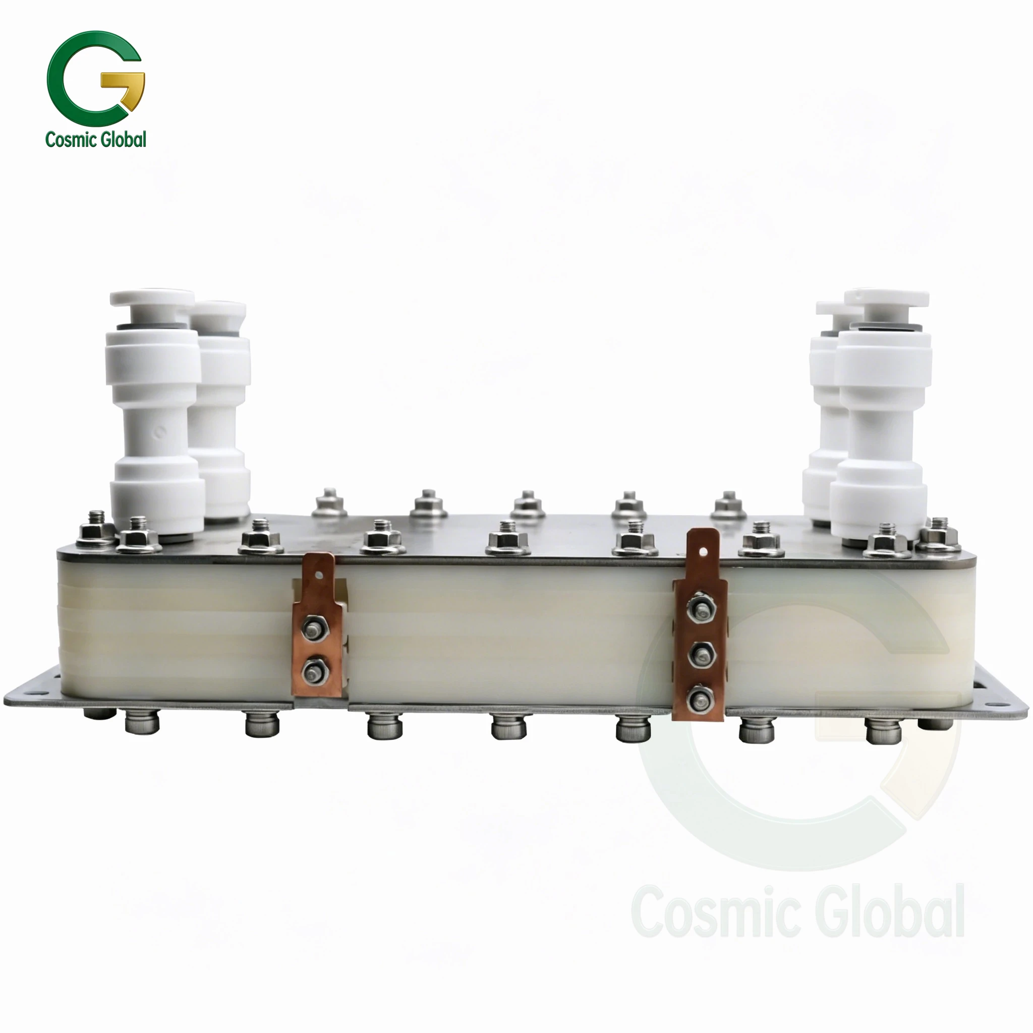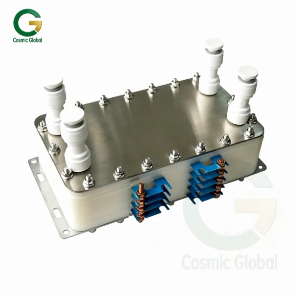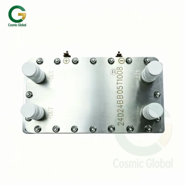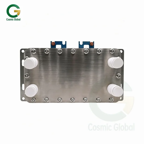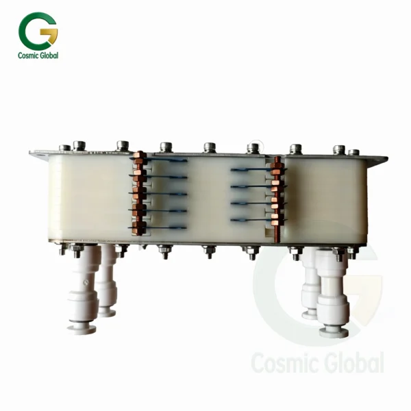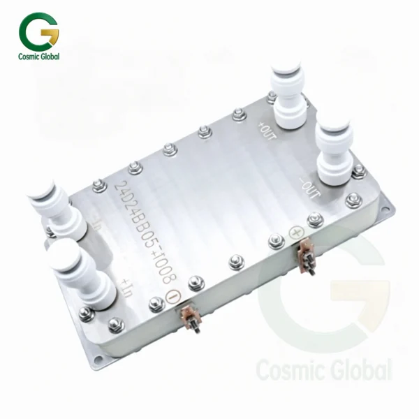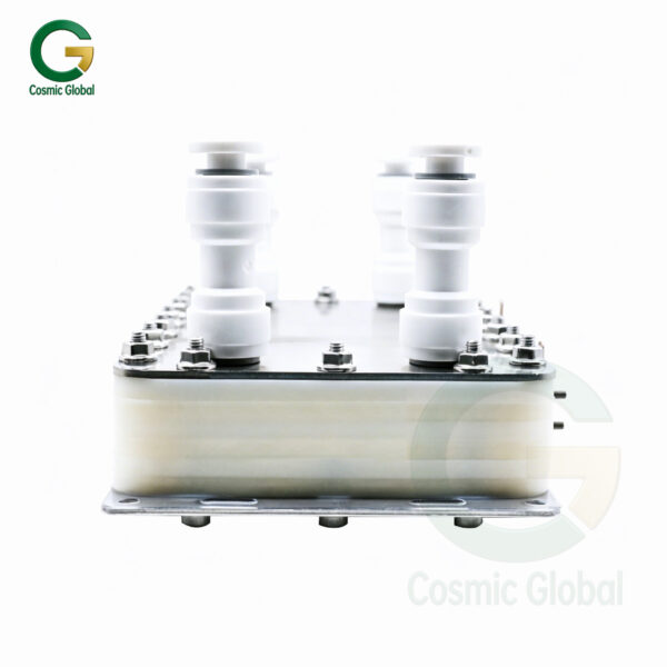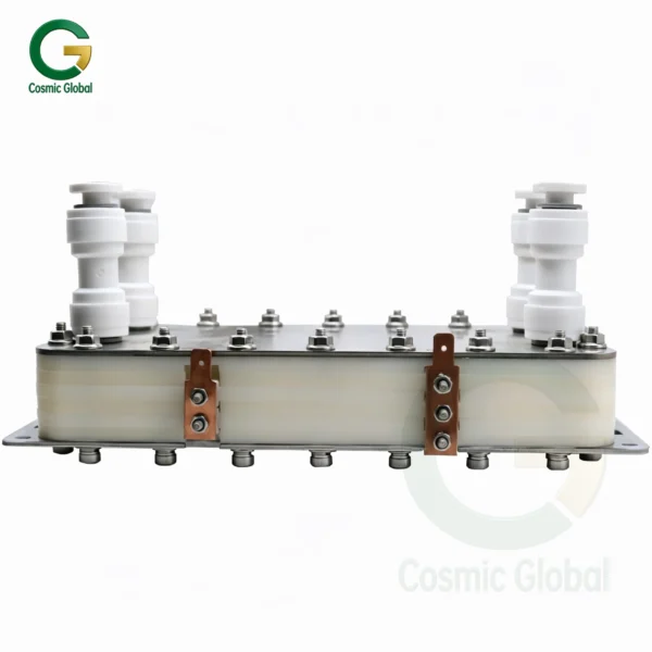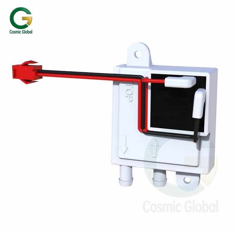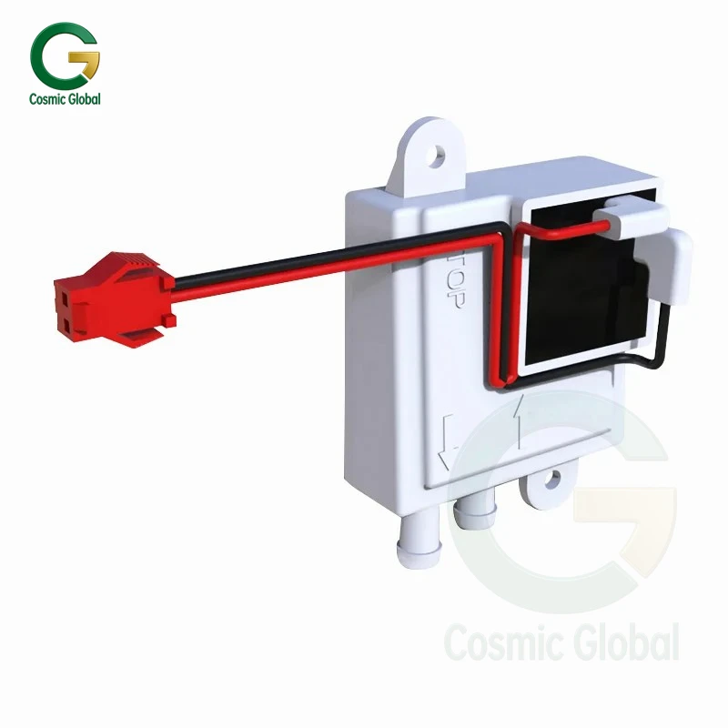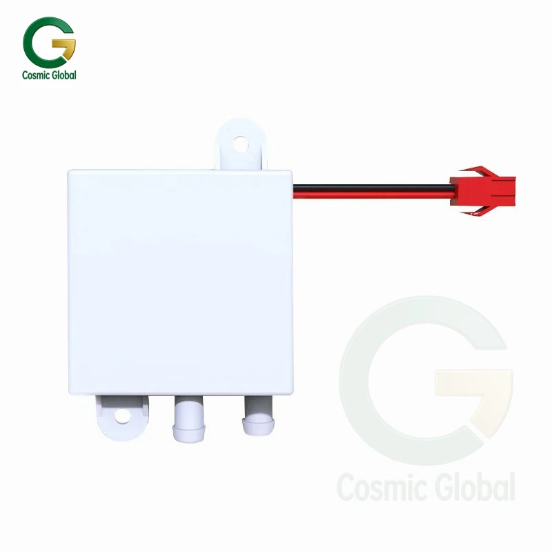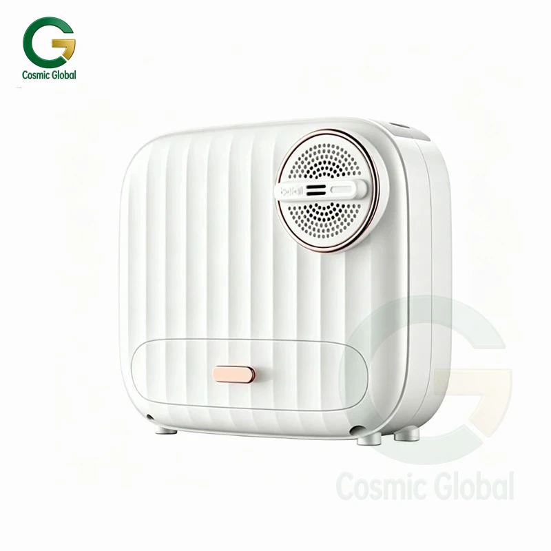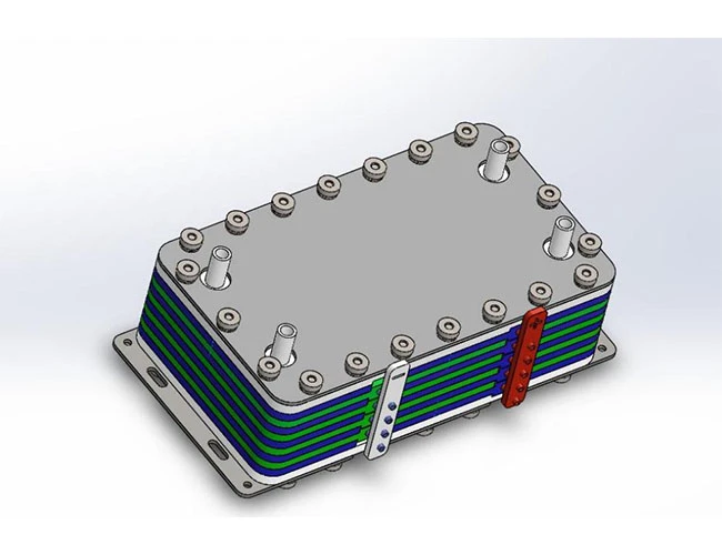
Features:
● High-efficiency electrolysis, integrated design, effective chlorine concentration of 10–120 ppm/L
● Precious metal titanium electrodes, environmentally friendly and pollution-free
● Multi-layer design, flexible adjustment
● Safe low voltage, ensuring safety
● Hypochlorous acid water with a pH of 2–4
Hypochlorous Acid Electrolysis Cells:
● Medical disinfection equipment
● Secondary water supply disinfection equipment
● Swimming pool disinfection equipment
● Production of disinfectant solutions for rinsing, cleaning, and soaking commercial and household tableware and sanitary ware
● Rinsing and soaking disinfection of fruits, vegetables, and raw foods
● Environmental spraying and wiping disinfection
Applications:
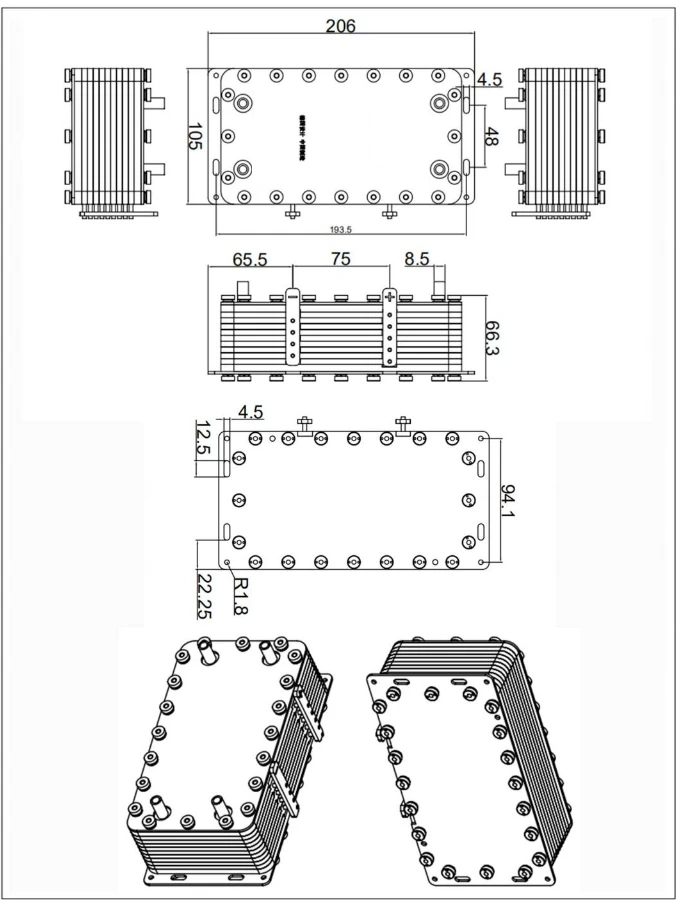
Installation Instructions:
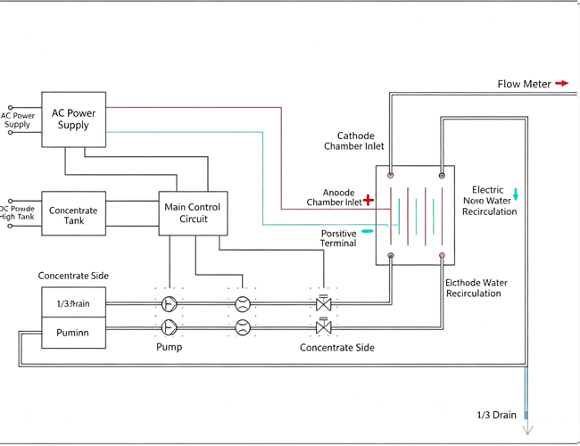
1. The electrolytic cell is powered by a constant-current power supply.
● The electrolytic cell requires a dedicated electrolytic power control system and an electrolyte supply control system.
● See the Basic Parameters Table for detailed requirements regarding auxiliary equipment.
● The power supply system and the electrolyte supply system work in coordination. When water flows out of the electrolytic cell, the electrolytic power supply begins to deliver power.
This equipment requires three levels of protection:
● The constant-current power supply itself features overcurrent and overvoltage protection.
● Pressure monitoring of the piping requires the installation of a pressure relief device.
● The system must monitor the water flow into the anode and cathode chambers. If the electrolyte supply is interrupted, the power to the electrolyzer must be immediately cut off to prevent damage to the equipment.
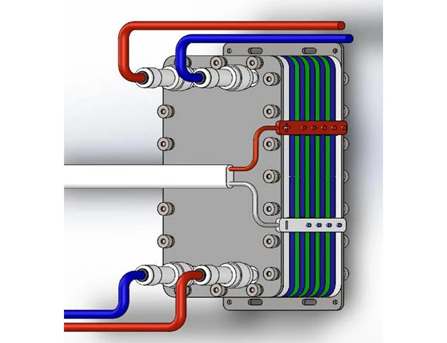
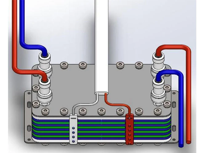
2. Use 3″ quick-connect fittings to connect the inlet and outlet of the electrolytic cell.
3. The positive and negative terminals of the electrolytic cell can be connected using 6.3mm spring-loaded terminals. Select the appropriate copper-core flexible wire based on the number of layers.
4. The electrolytic cell must be installed vertically, with the inlet at the bottom and the outlet at the top to facilitate venting.
Note: The inlet and outlet connections of the electrolytic cell are fragile. Please handle with care when installing or removing the connectors to avoid damage or breakage.
Basic Specifications:
| Items |
3 items |
5 items |
7 items |
9 items |
11 items |
| Power Supply Current |
0-5A |
0-10A |
0-15A |
0-18A |
0-22A |
| Power Supply Voltage |
0-36V |
| Operating Water Pressure |
≤0.2MPa |
| Operating Temperature |
0-40℃ |
| External Dimensions |
Length * Width |
206 mm*105 mm |
| Thickness |
35mm |
45mm |
55mm |
66.5mm |
76.5mm |
| Flow rate |
1L/min |
1-2L/min |
1-3L/min |
1-3L/min |
1-3/min |
| Available chlorine |
30ppm |
40ppm |
60ppm |
81ppm |
100ppm |
Layer number, current, and available chlorine value curves
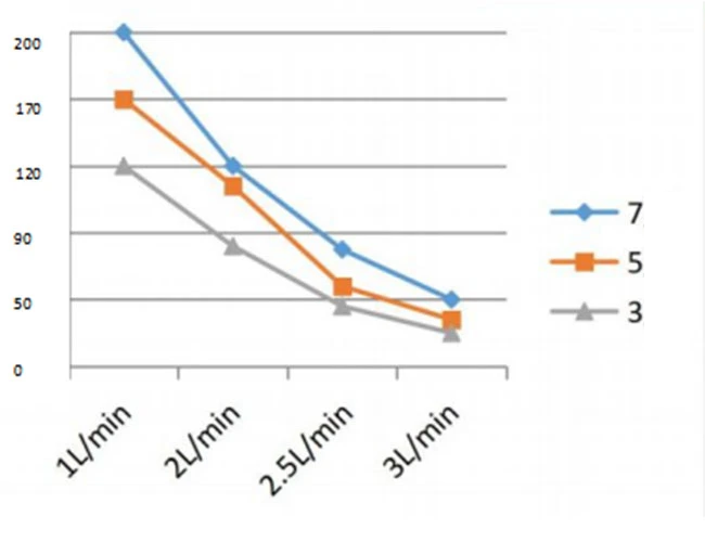
Flow rate — available chlorine (ppm)
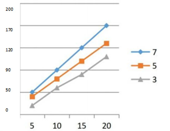
Current — Available chlorine (ppm)
Example of use
| Electrolyzer Type |
Effective Outflow Rate |
Salt Concentration |
Voltage |
Current |
Available Chlorine |
PH |
| Nine-piece ruthenium-iridium electrolyzer with film |
3L/min |
3% |
4.5V |
18A |
81ppm |
3-4 |
| 2.5% |
4.8V |
65ppm |
3-4 |
| 0.05% |
22-24V |
27ppm |
6-6.5 |
| 0.03% |
26-30V |
12ppm |
6-7 |
Environmental Adaptability
Refer to the requirements and test methods for sealing performance, water pressure resistance, electrolytic performance, and durability in CAS 124-007, GB12176-1990, and GB/T 19774-2005 standards.
Relevant Test Items: (The following are tests on 5 pieces of precious metal coated electrolytic cell samples)
| Serial Number |
Test Items |
condition |
Remark |
| 1 |
Sealing performance |
Seal the working water and drain outlet of the electrolytic cell, and apply 0-0.2 MPa water pressure to the inlet and maintain it for 1 minute without leakage. |
booster pump |
| 2 |
Water pressure resistance |
Seal the outlet of the electrolytic cell, apply a water pressure of 0.2 MPa to the inlet and maintain it for 5 minutes. The electrolytic cell should not be damaged or leaking. |
booster pump |
|
3 |
Electrolytic performance |
For water supply to the electrolytic cell, the water source should have a dynamic water pressure below 0.2 MPa:
1. With an inlet flow rate of 2-55 L/min and a 5‰ concentration of dilute brine, and an electrolysis current of 10 A or higher, after 10 seconds, fill a container with at least 150 ml of the electrolyzed water and measure the effective chlorine concentration using an effective chlorine tester. The effective chlorine concentration should meet the specified value. |
The available chlorine at the anode outlet during electrolysis is 60 mg/L. |
| 4 |
Durability performance |
Provide a water source with a flow rate of 2L/min and a dynamic water pressure of less than 0.2Mpa to the inlet side. Under the condition that the electrolysis current is the rated current of 3A, perform 15 minutes of forward and reverse electrolysis as one cycle, and continue for 1500 cycles. After a total working time of 750 hours, there are no problems with items 1, 2, and 3, and the performance meets the requirements. |
DC power supply, water pump |
| 5 |
Low temperature storage test |
After being left to stand at sub-zero temperatures for 4 hours, the appearance, structure, and main properties of the sample met the requirements. |
Low temperature test chamber |
| 6 |
Packaging vibration test |
10-30-55Hz (sine vibration), amplitude 0.75m, 1 octave/min, 15min each in the X, Y, and Z directions (total 45min) |
Variable Frequency Vibration Meter
(Standard Product Packaging) |
Service Life:
Under normal atmospheric pressure and with an external standard power supply and water source, the continuous operating time during intermittent operation (60 minutes of power-on, 30 minutes of power-off) should be ≥5000 hours.
Reliability Requirements:
The reliability of the electrolytic cell is expressed in terms of Mean Time Between Failures (MTBF): MTBF ≥ 5,000 hours.
Safety Performance:
a) The electrolytic cell uses low-voltage DC input, so there is no risk of electric shock or fire due to temperature rise;
b) When used correctly, the electrolytic cell should not suffer any damage or leakage;
c) When used correctly, the accessible parts of the electrolyzer should not be live.
Product Identification:
Model, Standard, Serial Number (unique)
Packaging, Transportation, and Storage
1) Shipping Packaging
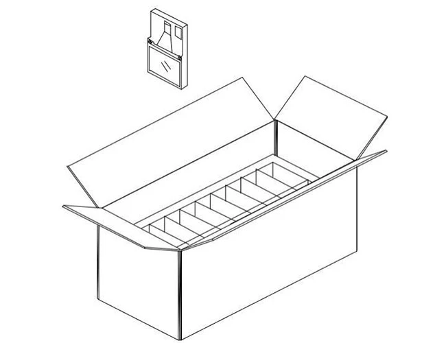
Packaging Dimensions: 570 (L) × 270 (W) × 280 (H) mm
Packaging Weight: 5 kg
Packaging Quantity: 5 units (each individually packaged in a bubble wrap bag)
2) Sample Packaging
Packaging Dimensions: 230 (L) × 120 (W) × 55–115 (H) mm
Packaging Contents: 1 set (packaged in a self-sealing bag)
3) Transportation and Storage
Avoid impact and exposure to rain or snow during transportation; do not store together with chemicals or damp items.
Outer Packaging Box Dimensions Diagram: